Input Devices
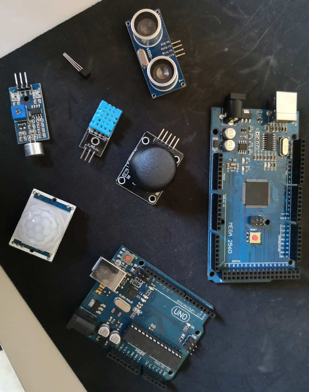
This week we work on some Input Devices, but wha's this devices?
This devices family are mostly Sensor devices, transmiting an analogic or digital signal due to a external changement.
Cause of the Pandemic stay at home mesure in France, this week i don't make my own PCB, but at less i work on a Arduino board.
Let's Start.
Joystick :
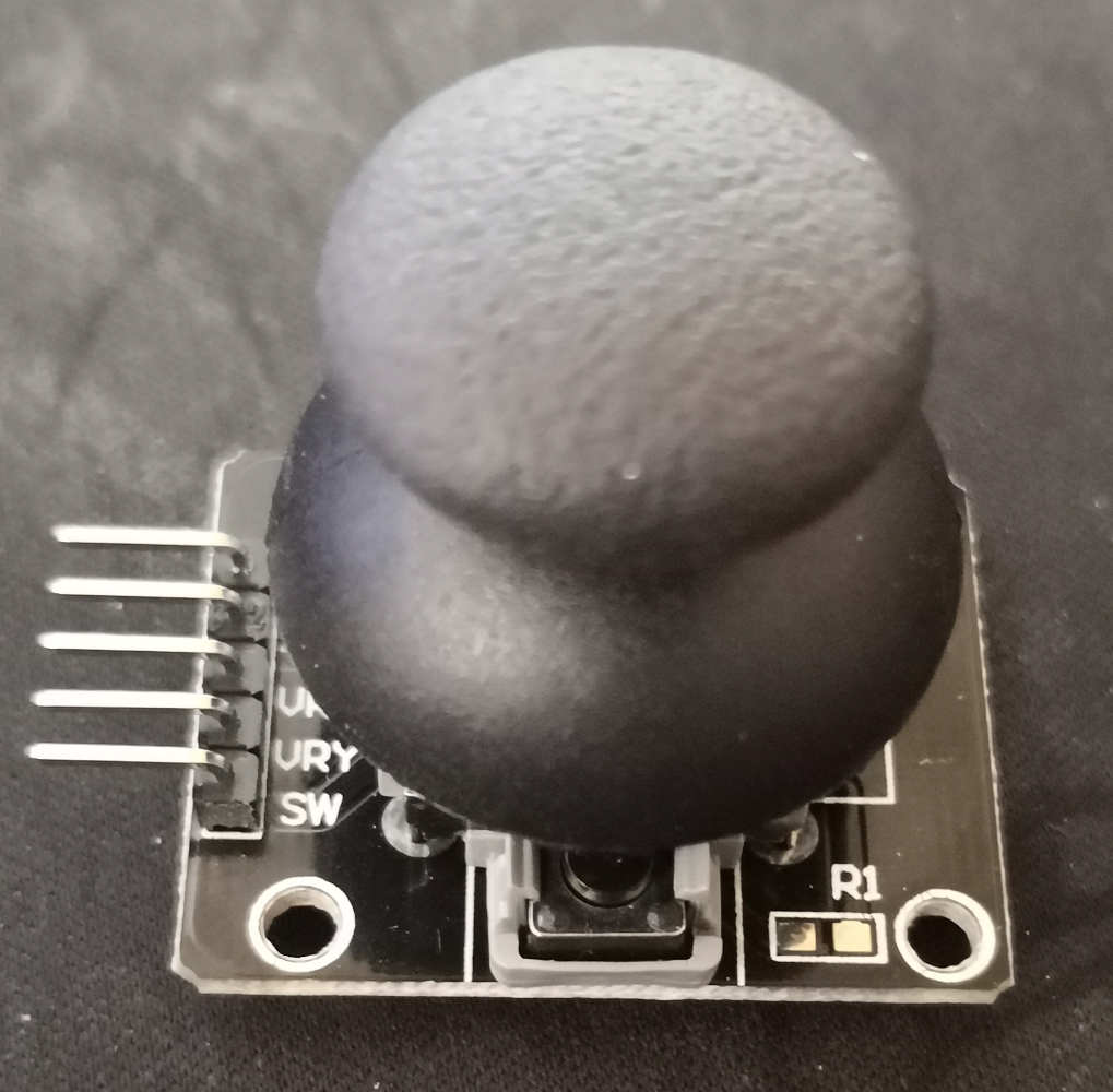
The First input i try is a Joystick, it's work with 2 potentiometer, one on the Y axis & the second one on the X axis, capturing the position of the joystick rotation.
I work for all the sensor on the arduino IDE.
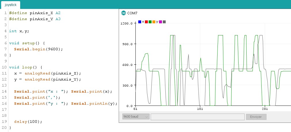
After looking on internet some tutorial i write this code:
#define pinAxis_X A2
#define pinAxis_Y A3

int x,y;

void setup() {
Serial.begin(9600);
}

void loop() {
x = analogRead(pinAxis_X);
y = analogRead(pinAxis_Y);

Serial.print("x : "); Serial.print(x);
Serial.print(',');
Serial.print("y : "); Serial.println(y);


delay(100);
}
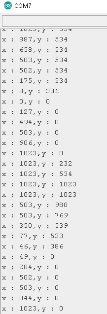
Serial.print commande to see the value on the serial monitor in my IDE.
I could see with this test the value change when i move the joystick. The joystick is a Analogique Input device he send different value due to is positionning.
Temperature :
For this week assignement i take a lot of fun, i have on my own stock a arduino kit with a lot of different sensor to try, let's try all. Each day a new one ^^.
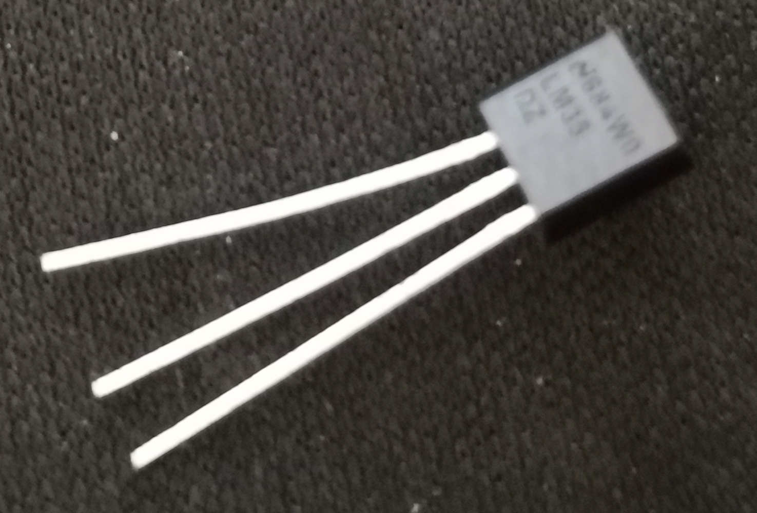
Today, the "LM35DZ" it's a analogic temperature sensor.
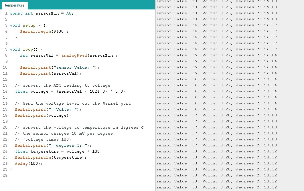
On is datasheet i see it's working between 0°C & 100°C and have linear +10mV/°C Scaale Factor, i use this for my code:
const int sensorPin = A0;

void setup() {
    Serial.begin(9600);
  }

void loop() {
    int sensorVal = analogRead(sensorPin);

    Serial.print("sensor Value: ");
    Serial.print(sensorVal);

  // convert the ADC reading to voltage
  float voltage = (sensorVal / 1024.0) * 5.0;

  // Send the voltage level out the Serial port
  Serial.print(", Volts: ");
  Serial.print(voltage);

  // convert the voltage to temperature in degrees C
  // the sensor changes 10 mV per degree
  // (voltage times 100)
  Serial.print(", degrees C: ");
  float temperature = voltage * 100;
  Serial.println(temperature);
  delay(100);
}
have some nice result, react when i put my finger on.
Motion :
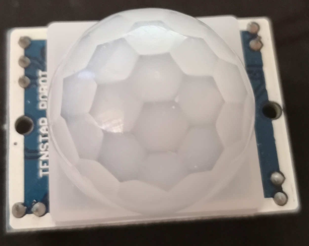
New day, new sensor. Today let's work with a InfraRed Pyroelectric motion Sensor.
This Sensor detect the motion of infrared warm waves, when he detect a move, he send a signal for a short moment, he juste need a little time to read another move.
code here
#define Pyr 3


void setup() {
pinMode(Pyr,INPUT);
attachInterrupt(digitalPinToInterrupt(Pyr),detection,CHANGE);
Serial.begin(9600);
}

void loop() {
}

void detection(){
if(digitalRead(Pyr)==HIGH){
Serial.println("Motion detect");
}
else{
Serial.println("No Motion");
}
}
Measurement :
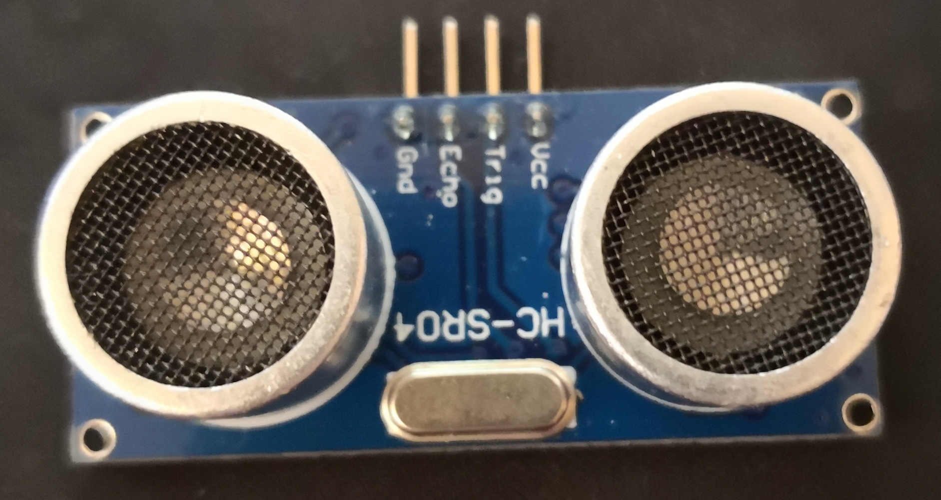
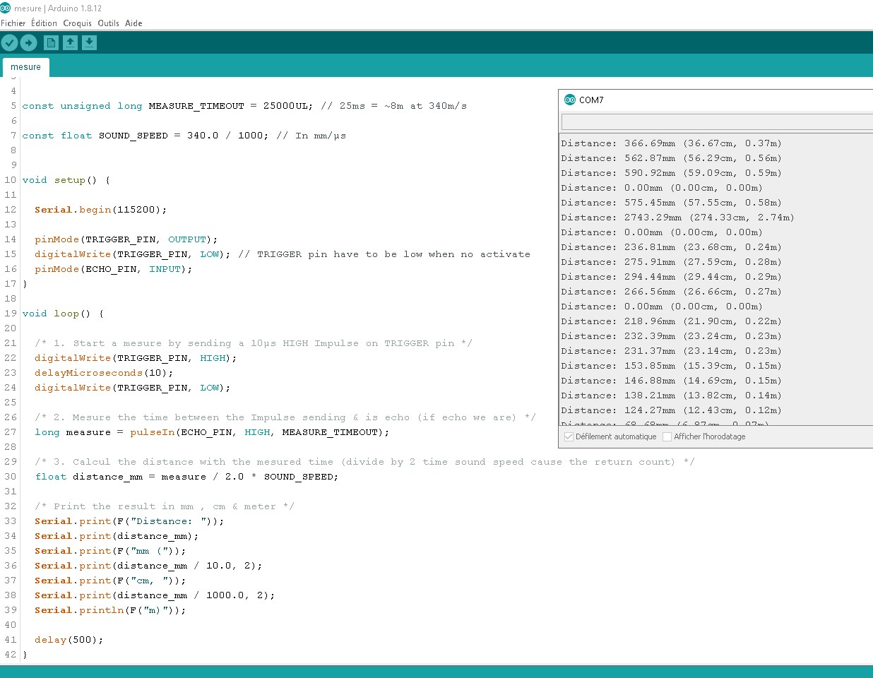
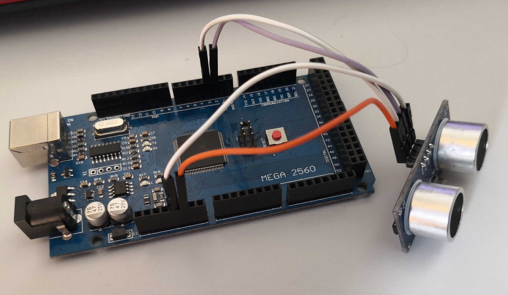
For measure a distance i use a Ultra sonic measure module, this sensor work by sending a ultrasound signal and waiting the signal back, for measure the time between sending & receiving.
this code need some calcul, is the reason is a quite more long ^^.
const byte TRIGGER_PIN = 2;
const byte ECHO_PIN = 3;


const unsigned long MEASURE_TIMEOUT = 25000UL; // 25ms = ~8m at 340m/s

const float SOUND_SPEED = 340.0 / 1000; // In mm/µs


void setup() {

Serial.begin(115200);

pinMode(TRIGGER_PIN, OUTPUT);
digitalWrite(TRIGGER_PIN, LOW); // TRIGGER pin have to be low when no activate
pinMode(ECHO_PIN, INPUT);
}

void loop() {

/* 1. Start a mesure by sending a 10µs HIGH Impulse on TRIGGER pin */
digitalWrite(TRIGGER_PIN, HIGH);
delayMicroseconds(10);
digitalWrite(TRIGGER_PIN, LOW);

/* 2. Mesure the time between the Impulse sending & is echo (if echo we have) */
long measure = pulseIn(ECHO_PIN, HIGH, MEASURE_TIMEOUT);

/* 3. Calcul the distance with the mesured time (divide by 2 time sound speed cause the return count) */
float distance_mm = measure / 2.0 * SOUND_SPEED;

/* Print the result in mm , cm & meter */
Serial.print(F("Distance: "));
Serial.print(distance_mm);
Serial.print(F("mm ("));
Serial.print(distance_mm / 10.0, 2);
Serial.print(F("cm, "));
Serial.print(distance_mm / 1000.0, 2);
Serial.println(F("m)"));

delay(500);
}
Really nice and fun play with this sensor.
Sound :
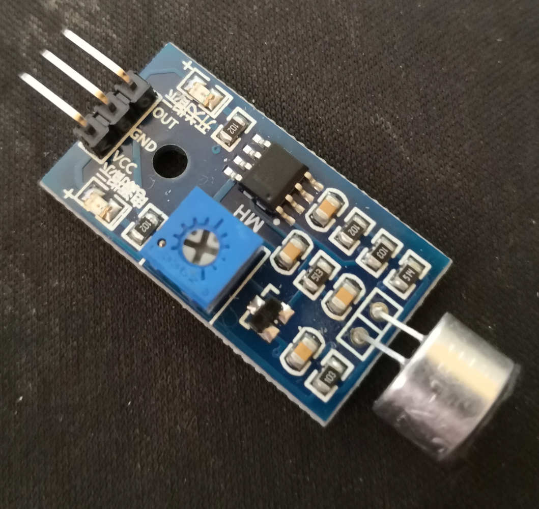
In my box i have a sound sensor, i'm going to test it.
when i writting the code i thinking this sensor work like a micro and could have a analogic signal but no just sending a high or low signal if detect sound.
#define pinMicro A2

int Sound;

void setup() {
Serial.begin(9600);
}

void loop() {
Sound = analogRead(pinMicro);

Serial.print("Sound : "); Serial.println(Sound);

delay(100);
}
Temprature & Humidity :
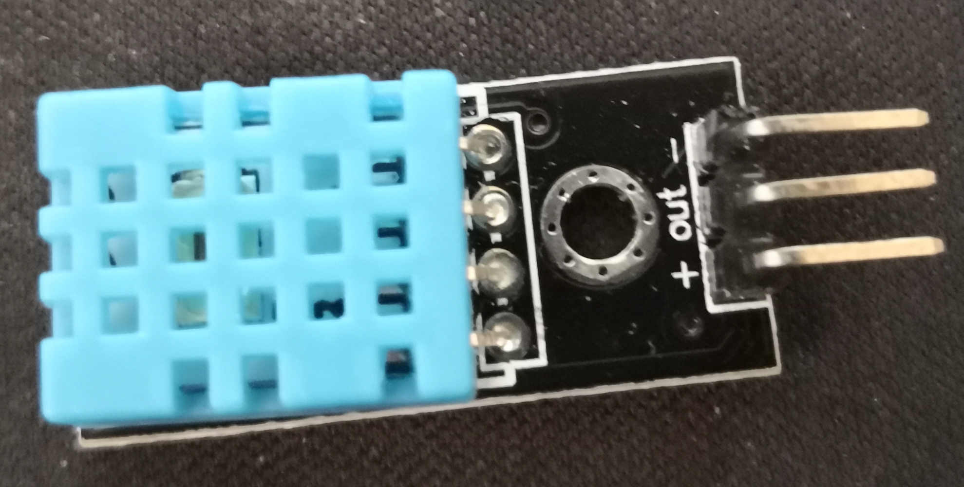
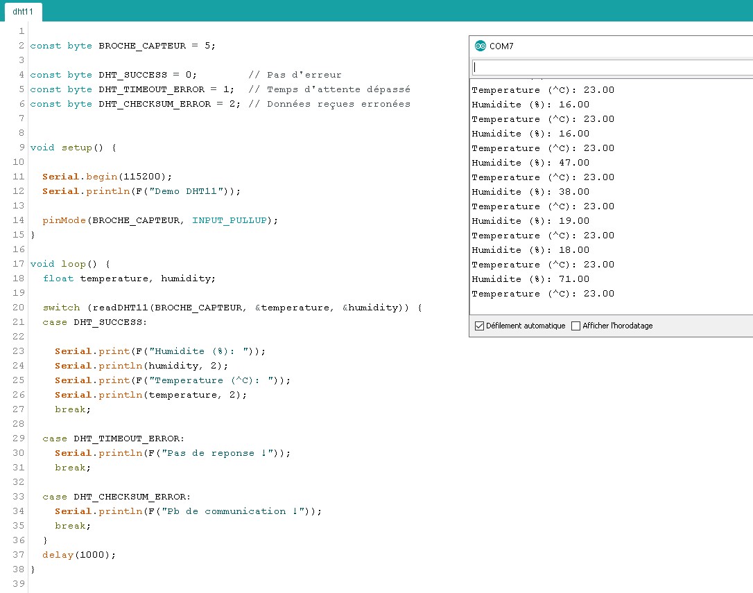
Last one, a DHT11 humidity & temperature sensor.
It's the kind of sensor i'm looking for my final project insie measurement.
After made some rechearche on it, i find a way for write this code :
const byte DATA_PIN = 5;

const byte DHT_SUCCESS = 0;
const byte DHT_TIMEOUT_ERROR = 1;
const byte DHT_CHECKSUM_ERROR = 2;


void setup() {

Serial.begin(115200);
Serial.println(F("Demo DHT11"));

pinMode(DATA_PIN, INPUT_PULLUP);
}

void loop() {
float temperature, humidity;

switch (readDHT11(DATA_PIN, &temperature, &humidity)) {
case DHT_SUCCESS:

Serial.print(F("Humidite (%): "));
Serial.println(humidity, 2);
Serial.print(F("Temperature (^C): "));
Serial.println(temperature, 2);
break;

case DHT_TIMEOUT_ERROR:
Serial.println(F("No return !"));
break;

case DHT_CHECKSUM_ERROR:
Serial.println(F("Communication error!"));
break;
}
delay(1000); // the DHT11 could make only one mesure by second
}

byte readDHT11(byte pin, float* temperature, float* humidity) {

byte data[5];
byte ret = readDHTxx(pin, data, 18, 1000);

if (ret != DHT_SUCCESS)
return ret;

*humidity = data[0];
*temperature = data[2];

return DHT_SUCCESS;
}


byte readDHTxx(byte pin, byte* data, unsigned long start_time, unsigned long timeout) {
data[0] = data[1] = data[2] = data[3] = data[4] = 0;

uint8_t bit = digitalPinToBitMask(pin);
uint8_t port = digitalPinToPort(pin);
volatile uint8_t *ddr = portModeRegister(port);
volatile uint8_t *out = portOutputRegister(port);
volatile uint8_t *in = portInputRegister(port);

unsigned long max_cycles = microsecondsToClockCycles(timeout);

*out |= bit;
*ddr &= ~bit;
delay(100);


*ddr |= bit;
*out &= ~bit;
delay(start_time);

noInterrupts();


*out |= bit;
delayMicroseconds(40);
*ddr &= ~bit;


timeout = 0;
while(!(*in & bit)) {
if (++timeout == max_cycles) {
interrupts();
return DHT_TIMEOUT_ERROR;
}
}

timeout = 0;
while(*in & bit) {
if (++timeout == max_cycles) {
interrupts();
return DHT_TIMEOUT_ERROR;
}
}

for (byte i = 0; i < 40; ++i) {

unsigned long cycles_low = 0;
while(!(*in & bit)) {
if (++cycles_low == max_cycles) {
interrupts();
return DHT_TIMEOUT_ERROR;
}
}


unsigned long cycles_high = 0;
while(*in & bit) {
if (++cycles_high == max_cycles) {
interrupts();
return DHT_TIMEOUT_ERROR;
}
}

data[i / 8] <<= 1;
if (cycles_high > cycles_low) {
data[i / 8] |= 1;
}
}

interrupts();


byte checksum = (data[0] + data[1] + data[2] + data[3]) & 0xff;
if (data[4] != checksum)
return DHT_CHECKSUM_ERROR;
else
return DHT_SUCCESS;
}
More complicate at all the other i write for the moment, but it's work.
But not a lot of precision on this sensor.......
I think i have to think about a more precise solution....
For the final project:
For th final project i finaly choose to work with a SI7020 sensor
This sensor is a I2C Humidity & Temperature Sensor with some nice caracteristique:
- ± 4% of precision Relative Humidity on a 0 - 80% range of RH
- 0 to 100% RH operating range
- ± 0.4% °C accuracy of the Temperature Sensor
- -40 to +125 °C operating range
- A wide operating voltage (1.9 to 3.6 V)
- Low power comsuption: 150µA active current & 60 nA standby current
- Factory-calibrated
You could find all the work i made on it Here.
Group Assignement (Due to Pandemic i'm lonely on my group but no problem):
For the group assignement we have to probe a signal using a osciloscope. A great thanxs to my wife, borowing for me to is work (high school technical & research assistant) some material ^^.
For start i try a piezzo sensor (Datasheet) for sense a heart beat on the osciloscope.
This Sensor show me a lot of noise when running but when i stop the capture i have a really nice analogic weave of a heart bit.
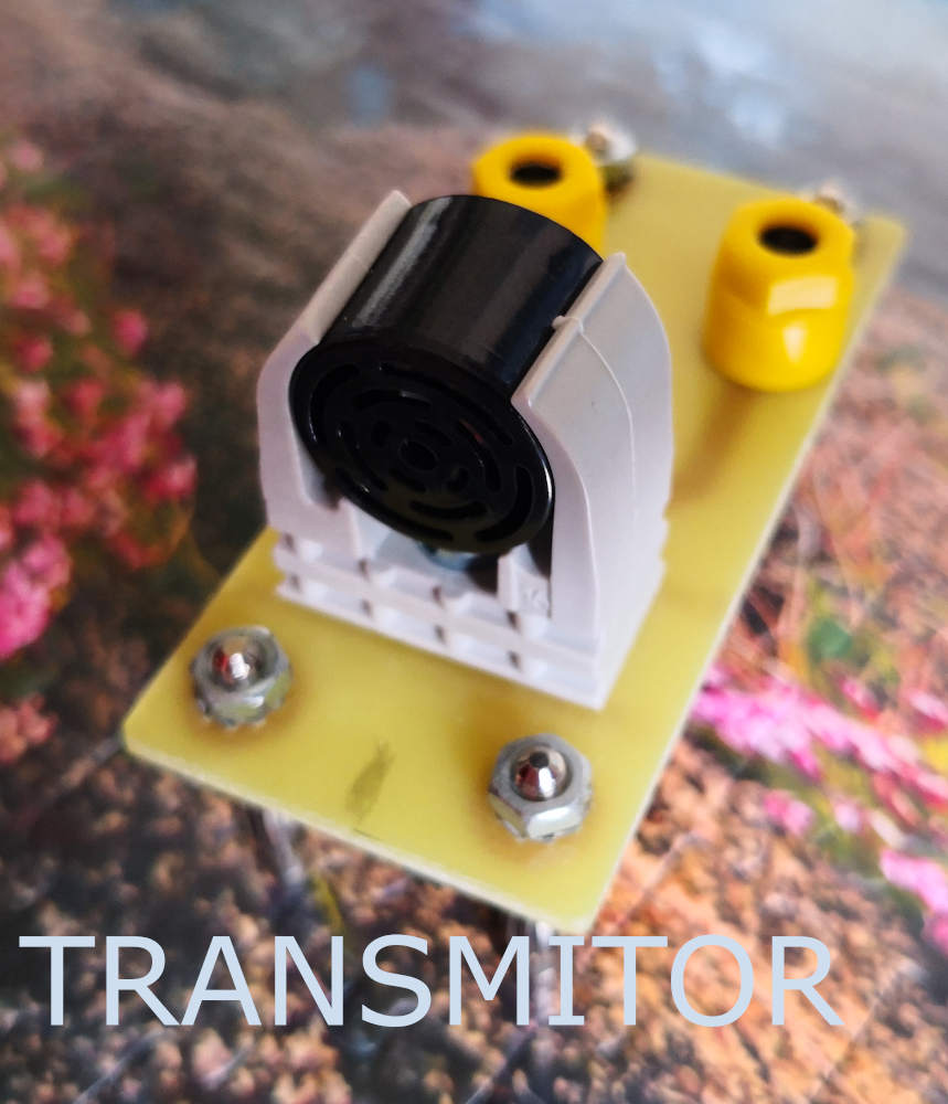
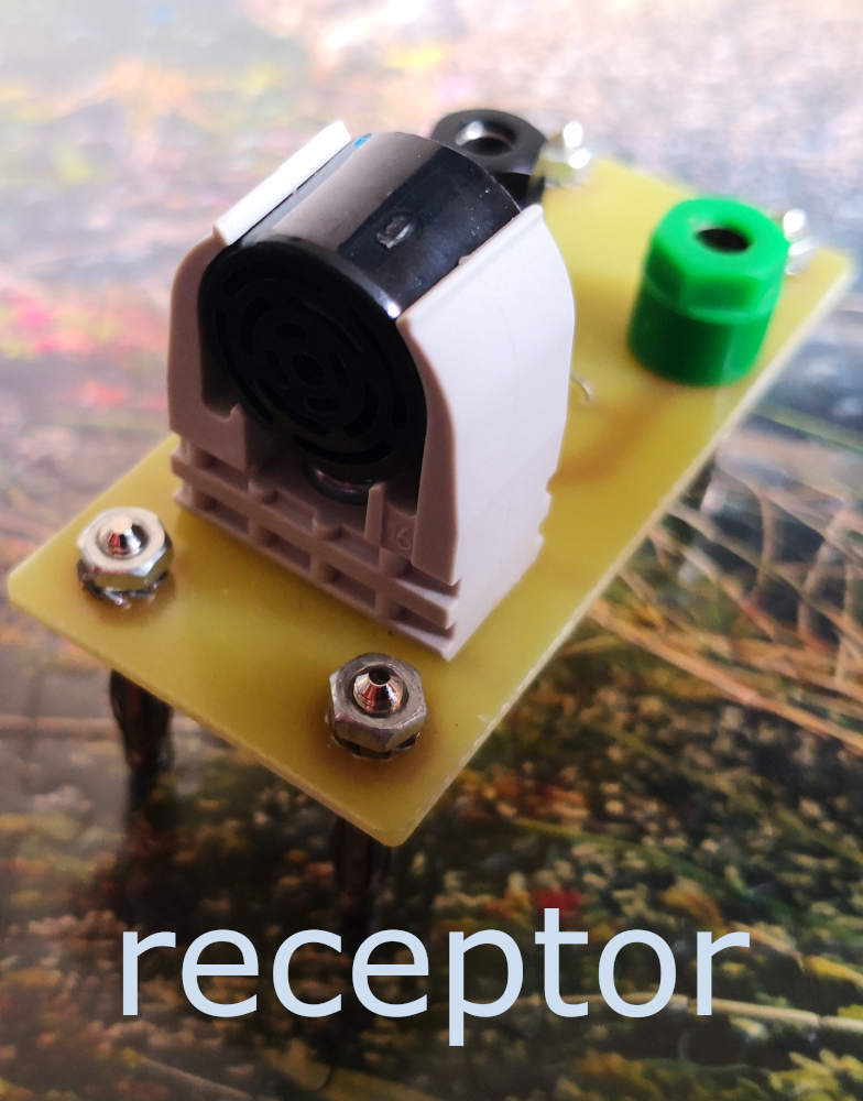
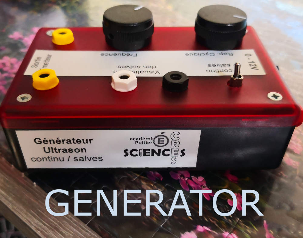
After i try a more complex assembly, it's a emiter & receiver system make for show to students the visualisation of ultrasound wave.
With this system i could clearly see the digital signal send & received on a analogic wave, with a short delay du to distance. (if we want we could measure the distance by calculating this delay.)
